 Digital Slave Flash
Thanks to Wing Joe, for translating my original Dutch version into English! Apologies for not yet translating also the titles of the pictures into English.
I have an old flash unit, but my digital camera does not have a flash connection. Anyway I prefer to not have a flash unit mount on the camera because I am concerned about red eyes. I have built a slave flash control module that fits under my flash unit, and it triggers my slave flash when my camera flashes.
Sorry, I do not have the time to make these devices on demand. However, ready-made versions are more affordable nowadays, eg at Porters. More links to do-it-yourself slave flashes at the bottom of this page.
This would not be difficult if my camera flashed only once, but it flashes a second time about two tenths of a second later. The effect is that the photo becomes darker instead of lighter: the flash goes off during the first camera flash which is used for measurement, so the camera thinks it has more than enough light, while during the actual taking the flash is already exhausted. (This is the reason that one sometime reads about expensive, digital slave flash units being required for digital cameras, as they 'know' this behaviour). I thought that some simple electronic circuit could help to solve this problem.
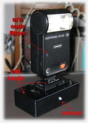
The concept: A control module with a phototransistor mounted under an old flash unit would sense the flash from the camera and trigger the flash unit when it senses the second flash ('digital slave flash with hot shoe').
If you have a camera where you can manually select single flash operation, there are simple low cost single flash units you can buy for use or for verifying your need to jump into a soldering project.
 The flash: overall idea
My camera first emits a 1 millisecond flash to measure the lighting conditions, and a main flash after a 170 milliseconds pause for the actual picture (see timing diagram signal 'A'). A monostable multivibrator (timer) is triggered upon sensing the first flash and remains on for about 300 milliseconds - lasting until the end of the full flash event (see diagram signal 'D'). If there is a second flash when the timer is in its on state, it will trigger the slave flash (see diagram 'E').
The circuit automatically returns (after about 300 milliseconds) to a ready state to sense a new first flash it there is no second flash encountered (for example in case someone else in the room uses a normal flash). This auto-reset is an advantage these timer-circuits have compared to a pulse-counting circuit.
The Sensor and Amplifier:
A phototransistor is a light-sensitive transistor whose current flow is dependent on the amount of light it senses. This transistor is connected to the + 5 volts supply (see plan) via a resistor. A flash will cause a larger flow through the phototransistor. The higher flow reduces the voltage and this voltage change is amplified by the next transistor.
 The amplifier and sensor are separated by a
capacitor so that only changes in the light level (the flash) generate a
signal. For the same reason, the output from the amplifier is isolated from the
pulse shaper by a capacitor. Constant ambient light will thus have no influence
on the subsequent circuit.
The amplifier and sensor are separated by a
capacitor so that only changes in the light level (the flash) generate a
signal. For the same reason, the output from the amplifier is isolated from the
pulse shaper by a capacitor. Constant ambient light will thus have no influence
on the subsequent circuit.
The 100K resistance to ground after the 10nF capacitor ensures that the input wave form to the pulse shaper is normally zero, and positive only when there is a flash. I have later added an 560Kohm resistor (see picture) to create a voltage divider to raise this threshold level to 0.75 volts. With this enhancement, the pulse shaper sensitivity is raised such that it will trigger with a .75 volts lower pulse. The RC time constant of the circuit has been designed approximately to match the duration of the flash (10 nF x 100K = 10-8 * 105 = 10-3 second = 1 millisecond)
The circuit is not totally insensitive for fast changing light in the surroundings. 100 Hertz flicker can disturb the circuit and trigger the slave to flash. This is visible by the fact the red LED is constantly on.
The Pulse Shaper:
 The signal from the sensor and amplifier is now fed to a
Schmitt-trigger circuit to generate a neat 0V/+5v 1 millisecond indication of
the flash (rest is + 5V, flash is 0 volts). This pulse is somewhat slowed down
by approximately 100 microsecond by the RC-network in the second
Schmitt-trigger circuit. This delay ensures that the falling edge of the pulse
occurs always after as the pulse from first Schmitt-trigger is complete. The
output from the second Schmitt-trigger will start the timer.
The signal from the sensor and amplifier is now fed to a
Schmitt-trigger circuit to generate a neat 0V/+5v 1 millisecond indication of
the flash (rest is + 5V, flash is 0 volts). This pulse is somewhat slowed down
by approximately 100 microsecond by the RC-network in the second
Schmitt-trigger circuit. This delay ensures that the falling edge of the pulse
occurs always after as the pulse from first Schmitt-trigger is complete. The
output from the second Schmitt-trigger will start the timer.
The Timer:
 The timer takes care of stretching the flash pulse to
about 300 to 400 milliseconds. This stretched signal of the first flash is
combined with the second flash pulse to trigger the slave flash unit (see
timing diagram). I would have preferred to use the 74HCT221 timer chip because
it reacts to the edge of a pulse. Unfortunately, these were not available and I
had to work with the 74HCT123 timer chip, which are level sensitive.
The timer takes care of stretching the flash pulse to
about 300 to 400 milliseconds. This stretched signal of the first flash is
combined with the second flash pulse to trigger the slave flash unit (see
timing diagram). I would have preferred to use the 74HCT221 timer chip because
it reacts to the edge of a pulse. Unfortunately, these were not available and I
had to work with the 74HCT123 timer chip, which are level sensitive.
To react to the falling edge, the signal is passed through an RC-network: a positive pulse gives a rising edge, but this has no effect because the input at rest is already positive. The falling edge however will start the timer with a time constant of approximately 0.3RC. This delay, as indicated on 'D' in the timing diagram, happens just after the first flash has expired.
At the second flash, the timer is still active. The AND gate provide the pulse to the slave flash by combining this indicator ('D') with the actual 2nd flash pulse 'A'.
A resistor on the active-low clear pin ensures that the clear is not activated during normal operation. At power-up the capacitor will pull down the clear for some time, making sure no erroneous pulse is generated towards the flash unit).
The red LED will indicate when 'D' is active (a flash has been seen). It can
also help to test the circuit without the actual flash unit connected, and to
check the level/sensitivity to ambient lights.
Firing the slave flash:
The flash is tripped by an electronic switch, a 'thyristor'. A small pulse on the gate can switch high voltage and currents. Given a pulse on 'E', the switch conducts and continues conducting until no more current flows through the switch. The switch is not sensitive to the length of the input pulse.
Power Supply:
I have used a simple voltage regulator chip for the 5 volts required by the digital circuits. The circuit uses a low-power 5 volt stabilizer (78L05, maximum 100 mA) chip and is connected to the 9 voltage battery via a switch S1. I added some capacitors to remove ripples and spikes and a green LED to indicate power on/off status.
The case:
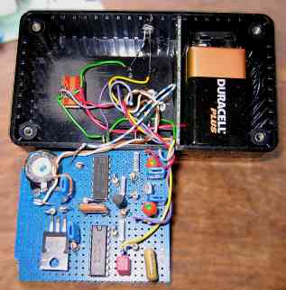 The biggest problem was finding a
socket for the slave flash. I found a suitable part in a cheap goods bin at a
photographer clearing sale for 1 euro. See the picture to see how the whole
control unit is housed.
The biggest problem was finding a
socket for the slave flash. I found a suitable part in a cheap goods bin at a
photographer clearing sale for 1 euro. See the picture to see how the whole
control unit is housed.
Set up:
In use, note that the device senses the first flash from the built in camera flash and fires the slave flash simultaneously with the second flash. If you set up both flash unit in front of the your subject, then the subject might be over-exposed.
What I do in such a situation is to underexpose the built in flash by 1 f-stop. I also set the slave flash to provide indirect lighting, for example to bounce the light off the ceiling. This reduces the amount of light entering the lens, and more on the context/subject. This is an advantage to me - better photos with the built in flash and no red eyes.
The Results:

 The first results: a
enlarging of photographs without and with the slave flash. In one corner of the
photo, it is obvious that the built in flash did not light up the entire area
(distance to curtain is approximately 8 meters). Both photographs are of course
unprocessed and with the camera in the same location.
The first results: a
enlarging of photographs without and with the slave flash. In one corner of the
photo, it is obvious that the built in flash did not light up the entire area
(distance to curtain is approximately 8 meters). Both photographs are of course
unprocessed and with the camera in the same location.
These are not the best photographs but are the first of some serial test shots from a randomly placed slave flash. Will show possibly better results if slave was placed optimally.
Ps: the yellow haze on background is from a lamp which provided additional light over and above that from the built in flash.
Extra
One possible improvement is a switch to also allow the use of this circuit with a classical camera without pre-flash. Disconnect the input of the HCT132 to output D (see timer diagram), en put a switch in-between: in the normal setting (with pre-flash), it reconnects to D, in the old-camera setting, it should connect to the signal of the clr-input to the HCT123 (basically always '+', so a pull-up always enabling the gate).
Another one: if you place the slave flash so that it does not sufficiently see the flash of the camera, it will not always trigger. I placed an extra sensor on a 3.5 mm mono jack plug, and put a chassis-part in the box. When I plug in the extra sensor, it switches off the internal one. The sensor is mounted on some copper wire, so I can bend it in any direction.
Some other versions/links by others
- An extensive Dutch page on slave flashes
- Slave Flash with PIC microcontroller
- Another slave flash based on a PIC processor, including pictures, print layout etc
- Another Digital Slave Flash
- Digital Slave Flash with selectable number of pre-flashes
Datum original version: 29 march 2004


op mijn site
| Voorpagina | |
| Moerman | |
| Hobbies | |
| Koken | |
| Keramiek | |
| Digi Foto | |
| Maken | |
| Flitser | |
| Hulpjes | |
| Dias | |
 | |
| Bewerken | |
| Kerst | |
| Planeet | |
| Winter | |
| Jazz | |
| WallPaper | |
| Spiek | |
| |
| PrintZelf | |
| Bergen | |
| EXIF | |
| |
| Lijstje | |
 | |
 | |
| Computers | |
| Archief | |
| Site Map |
